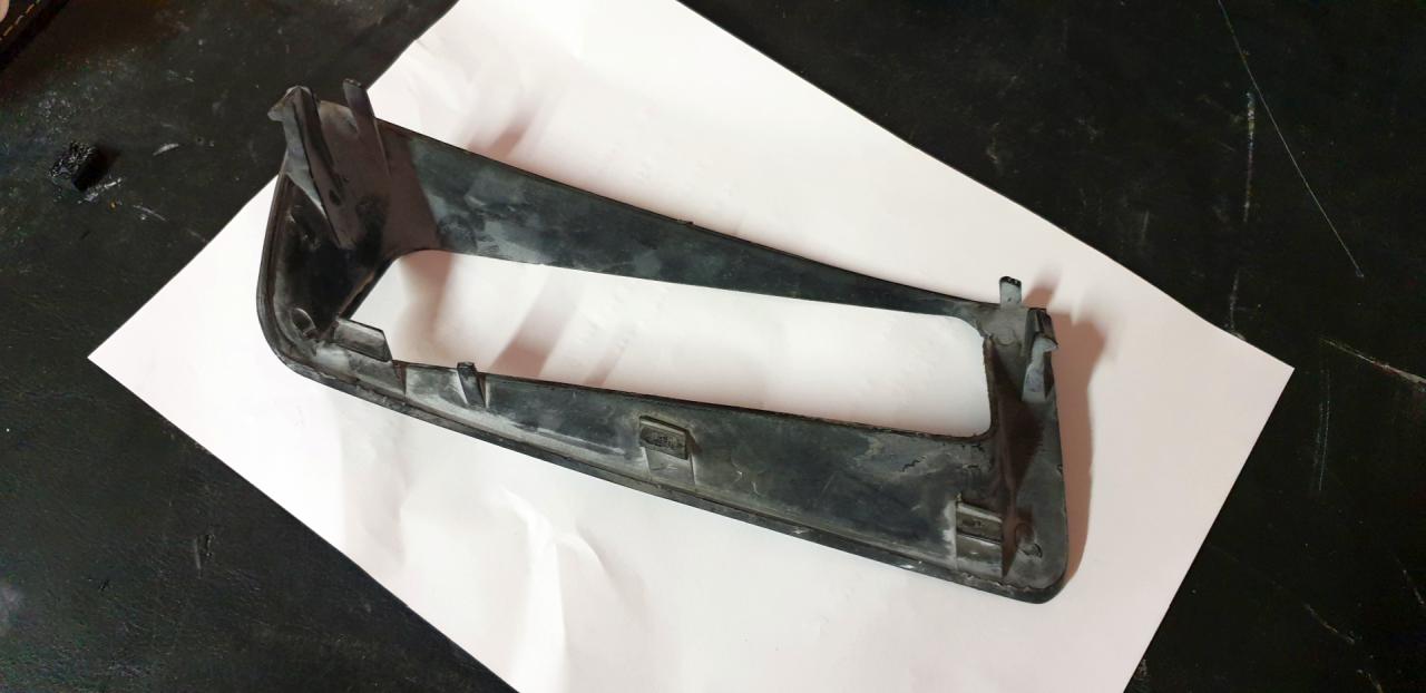
The original bezel itself came with some defects, due to its age, no surprise. Multiple screwdriver marks, scratches, cracked monting tab, possibly warped as well.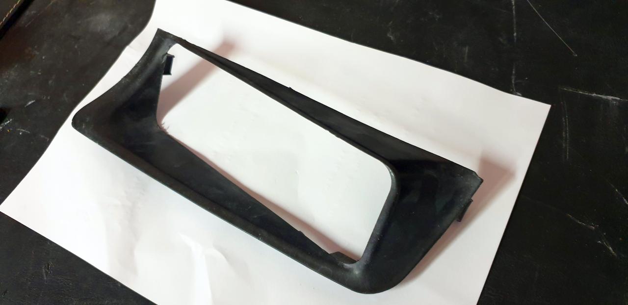
As preparation for scanning I glued the cracked areas back to position, cleaned the part and coated it with white matifying spray. White matte surface is necessary to get accurate scans of small parts and intricate areas.
After that I fired up my structured light scanning rig and started capturing the part. At this point i didn't give too much thoughts of how I will actually produce the new part, just concentrated on making a high quality scan of the original bezel. Usually it is not necessary to do a perfect scan of the part to be able to reverse engineer it, however due to my recent upgrades on the scanner rig, doing high quality scans is now a breeze and i quite enjoy using it. Later though this thinking paid out.
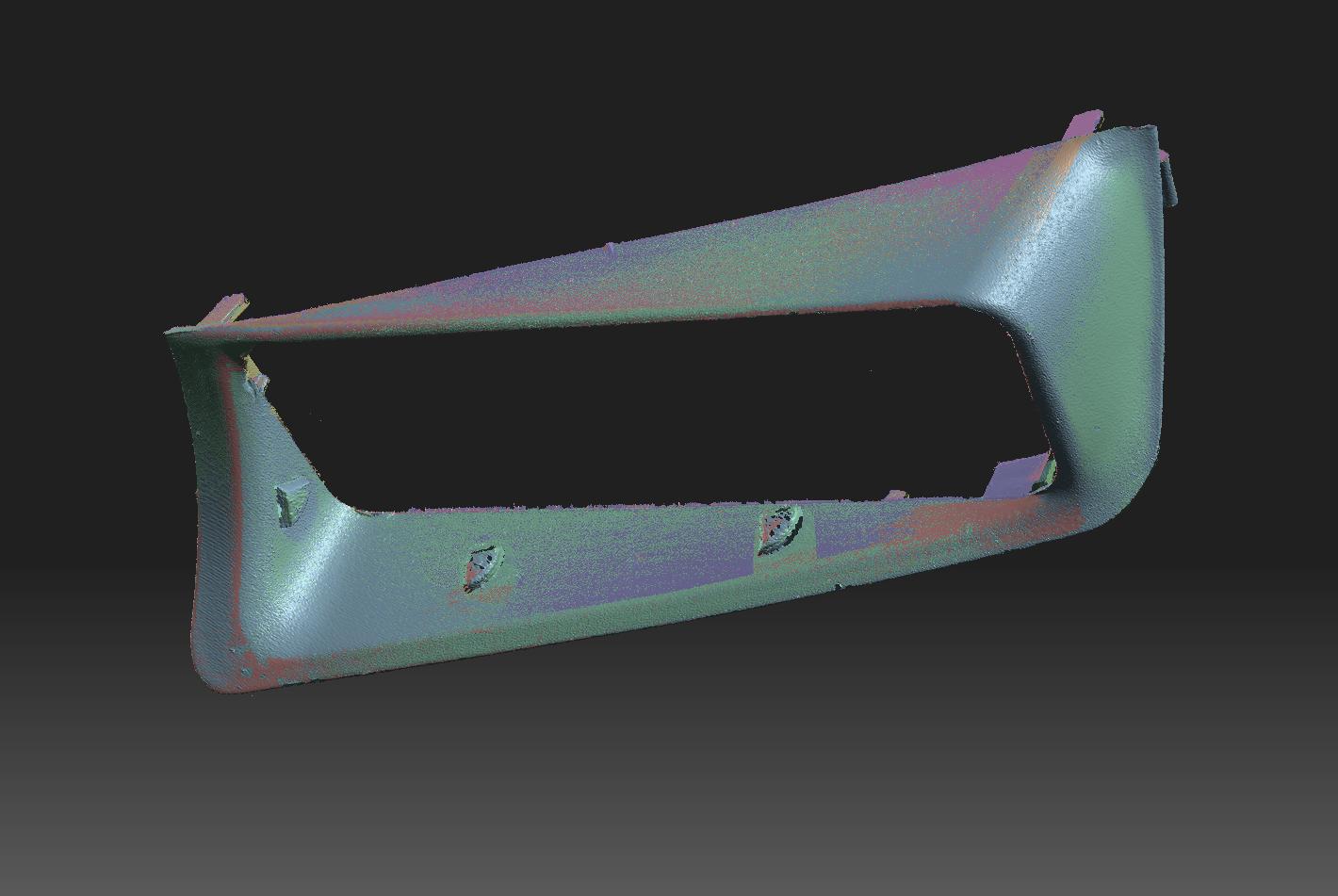
After I had the initial scan data, did the cleanup and alignment, I realized how complicated even the outer surface is. It had me thinking for quite a while, how could i define these surfaces parametlically in cad. I deemed manually finding the surfaces too much work for what it worth. Surface extraction did not work either because even I couldn't state a particular surface is a planar face or a large radius or could it be conical. After an hour of confusion it came to me that I may not necessarily have to remodel the part for a good reproduction. I gave a call to the customer, to ask if he plans to use the model to any other purpose or if he plans to order this part for multiple cars. Turned out this will be a one-off for that particular car, so I went ahead with my plan to repair the defects that came with the old part using polygon modeling tools.
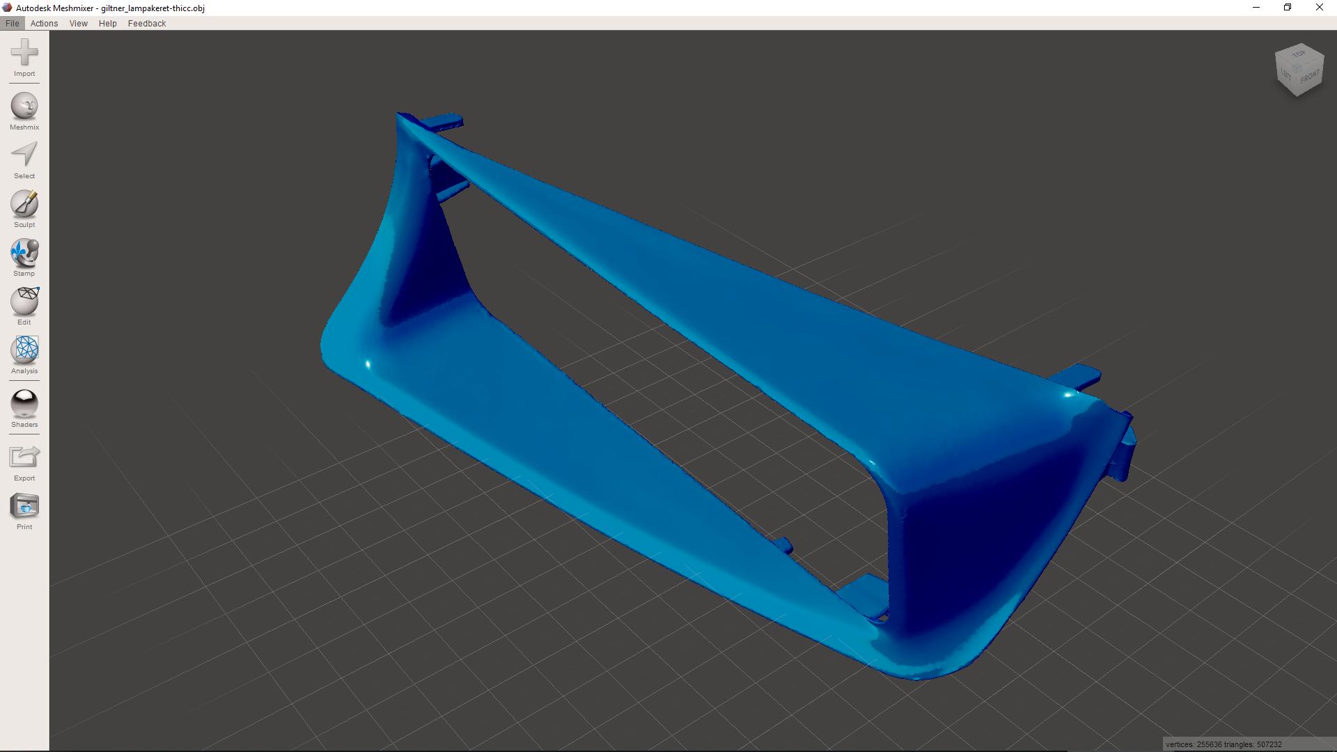
After done with the scan cleanup, hole filling, polycount decimation, the routine workflow, I thought I might look into checking out the geometry from a printing standpoint. After all, this part was designed for injection moulding and not for 3D printing.
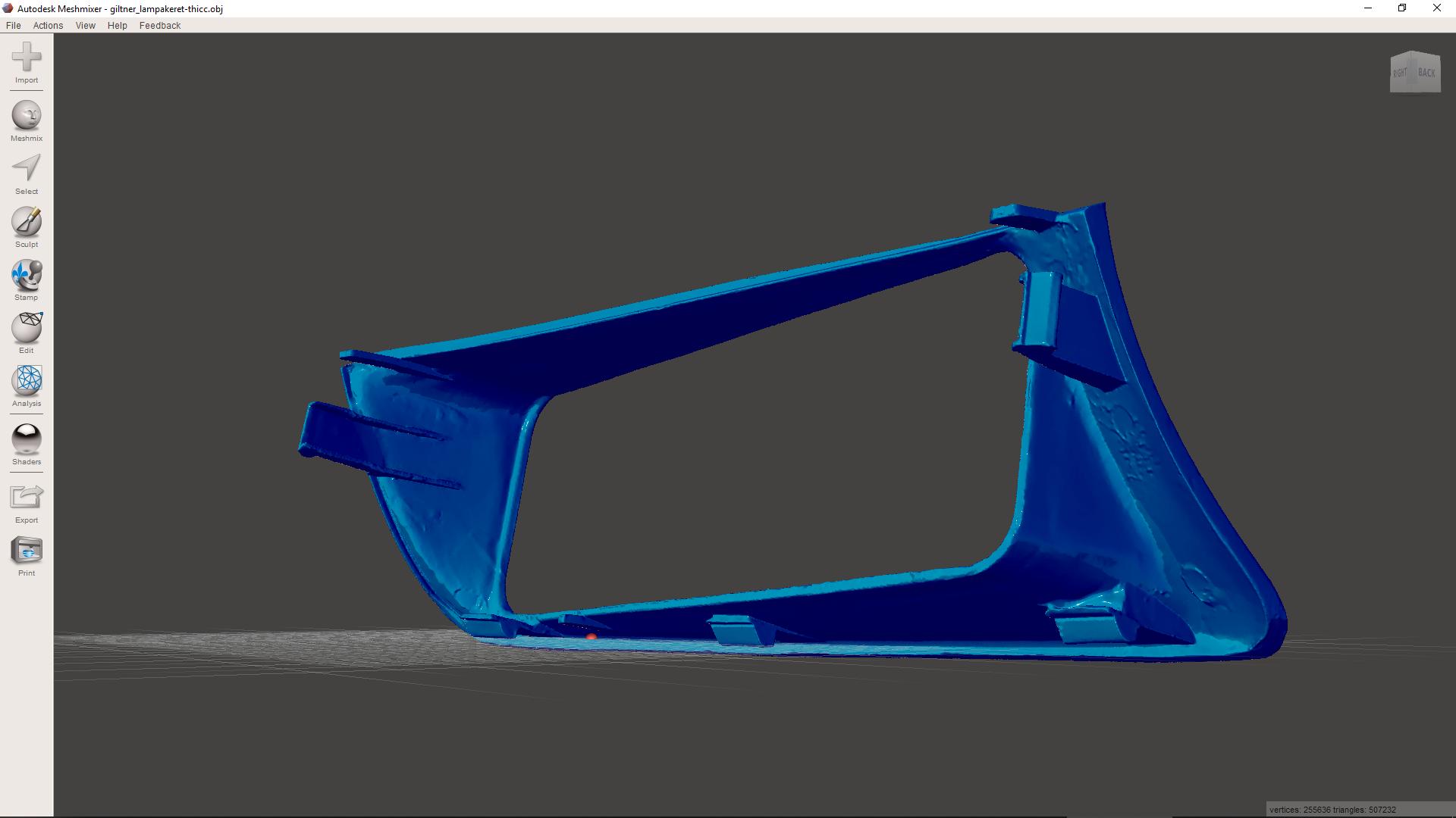
The original bezel is made of a soft material, possibly PP or a soft ABS blend so it was quite flexible, not at all like regular printed ABS. The model also had some really thin areas at the mounting tabs and hooks, which is not a problem with a homogenus injection molded plastic, but is a concern when talking about printed parts due to their more rigid, thus more brittle properties and the tendency to de-laminate between layer lines. To fight this, I thickened these areas by 0.5mm using meshmixer.
After that was done, the model was loaded to the slicer software, mirrored, positioned.
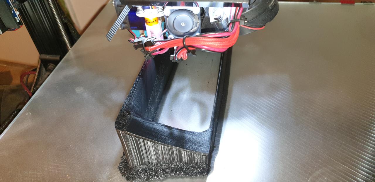
The bezel outer surfaces which are visible from the front of the car needed to be perfect, so the model needed to be printed with those areas facing up, and with that, the orientation is already decided. With the part having no flat area anywhere to start the print off of, using support material everywhere below the model was obligatory.
For the outer surfaces to print as smooth as possible, the layer height was set to a fine 0.12mm. A trick I use to get the strongest possible prints is that I print with 103% filament flow rate. This eliminates almost all airgaps betwen print lines. Also I print with higher nozzle temperature than the suggested number for the filament, this enables me to print faster than others in most cases and as bonus, it also makes my prints stronger. Despite all this, I was still looking at a lenghty print job.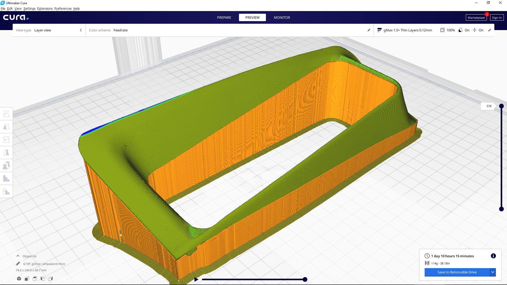
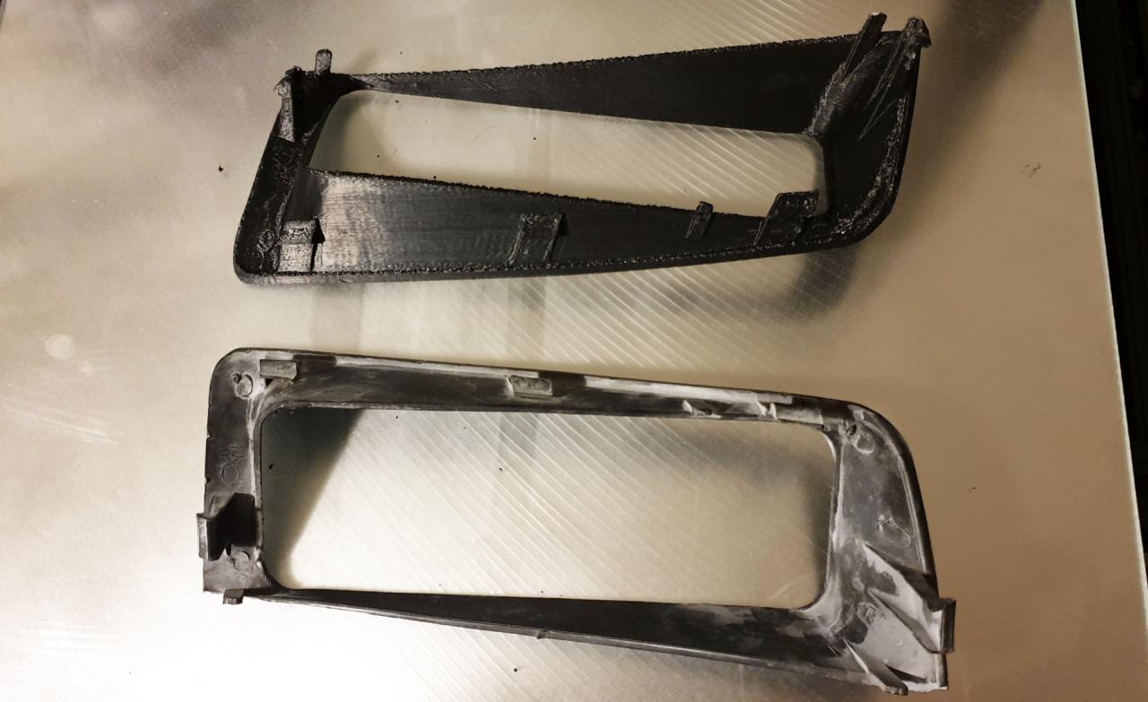
After 22hrs, the print was finished and after an additional hour of post processing, cleaning up the print, I was quite happy with the result. The outer surfaces, the tabs and hooks came out perfect, did not break or separate.
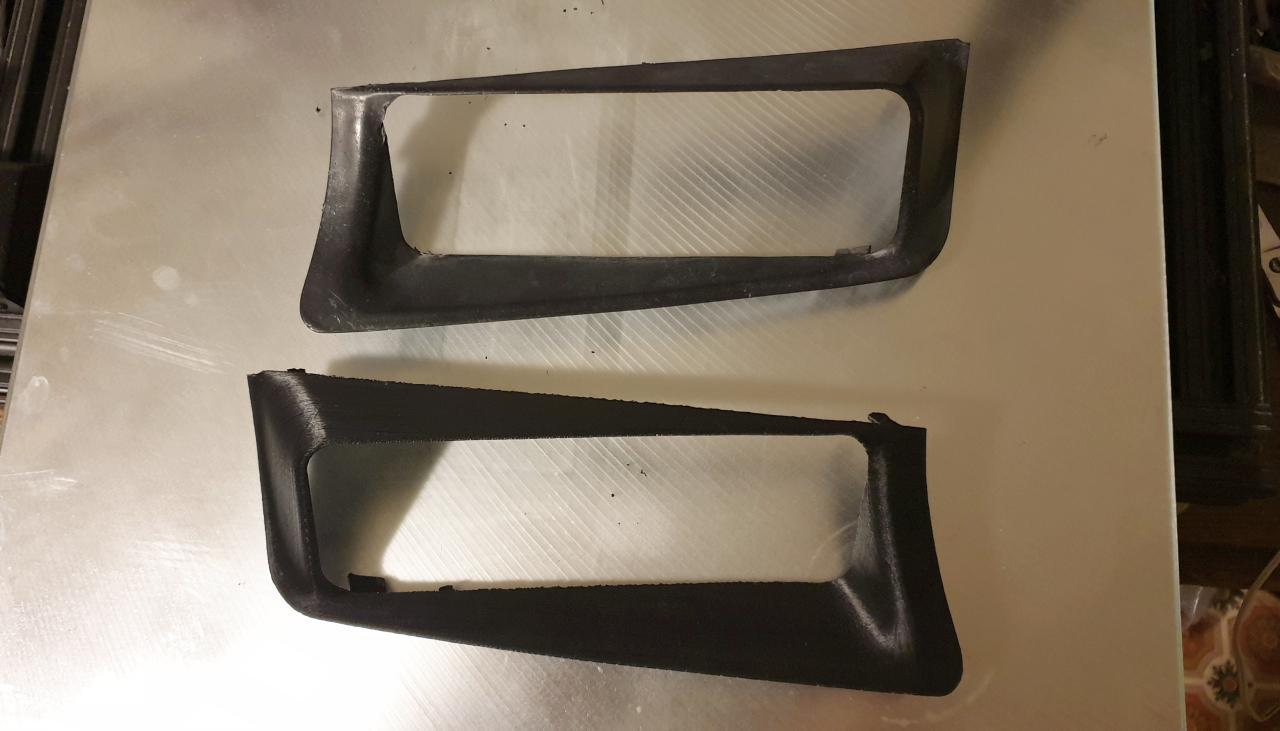
Putting the original and the reproduction part side by side, I think it will be convincing enough when painted and installed on the car.
Anyway, this was my firts time I did a printed part out of a 3D model which is not a part i designed in cad to be printed, but is basicly a raw scan of an object. Very new and intersting for me and I really enjoyed the process.